Overview
Digital signs are great way to navigate visitors to a building. Some places may benefit from a simple outline of the building with a “you are here” indicator, while others may require maps with routing that traverses floors. Some units have included maps of meeting rooms, class rooms, and restrooms. Others have even included maps of local dining, bus stops, and campus. This document contains the steps needed to configure any of these types of wayfinding maps.
Before You Begin
- The map(s) – These need to be in image format. A minimum resolution of 96dpi works best.
- Data source(s) – The locations that will be mapped out need to be listed somewhere. These can be placed in the wayfinding object itself (the map image), but it is much more dynamic if the data source is external and easily updated.
Add the Wayfinding Content
Note Never change the size or resolution of a map image once points are plotted on it. Doing so will cause the location points to no longer line up with the image.
- Log into Content Manager and select your unit's connection.
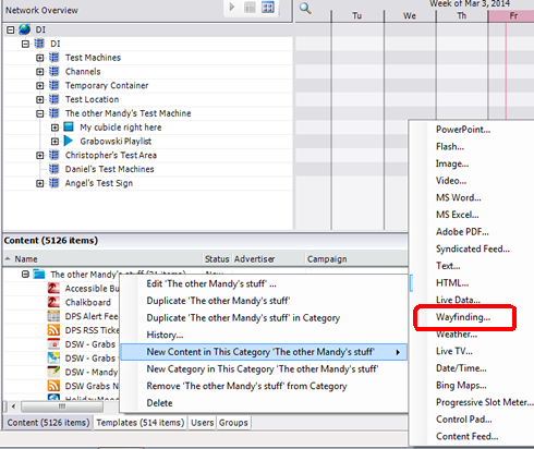
- From the Content category in the Content section of Content Manager, right-click on the Content category for your unit, and select New Content in This Category " [name of category]" > Wayfinding…<
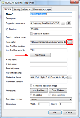
- Populate the name field with an easily recognizable name.
- Click the ellipse button at the end of the Floor paths field.
- Click the Add button.
- Browse the folder containing the map images and select the map to add it.
- Repeat steps 5 & 6 for additional map images.
- Click OK to return to the wayfinding properties.
- Ignore the You Are Here Location/Variable for now.
- Click Wayfinding.
>
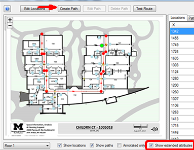
The Wayfinding Window
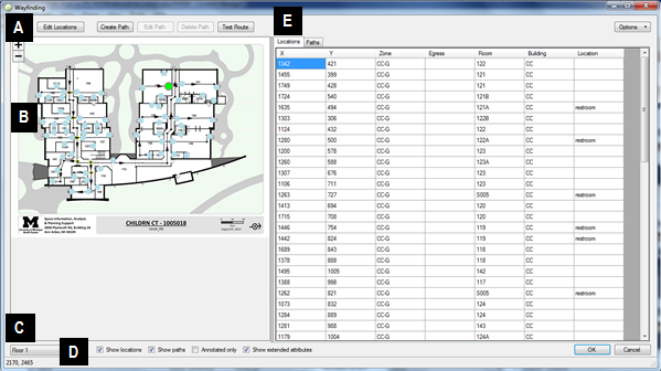
- The top action buttons:
- Edit Locations will add points on the map to be mapped to
- Create path will add paths that connect to the locations.
- Edit path will modify an existing path.
- Delete path will delete an existing path.
- Test Route will attempt to connect to points chosen by the user via the paths that have been laid out.
- The map will show the currently selected image. Locations will appear as gray dots. The currently selected location will appear green. Paths will show up as black lines with arrows. The currently selected path will appear blue. The + and – symbols allow the user to zoom in and out while not modifying locations or paths.
- The bottom view options:
- The Floor pull down allows users to switch the currently active map.
- Show locations/path will toggle path and location visibility on the map.
- Annotated only will hide locations, path endpoints, and intersections.
- Show extended attributes displays egress and zone information in the right side columns. This should be enabled every time locations or paths are edited.
- The numbers below the floor indicate the X,Y coordinates for where the mouse cursor is hovered over the map.
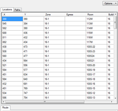
- The Locations Tab:
- The locations tab shows the X,Y coordinates, zone, and egress information for each point plotted on a map. Additional columns can be added via the options menu above.
- The paths tab shows the name and zone of each path on the map.
- The route tab at the bottom displays information about any test routes performed on the map.
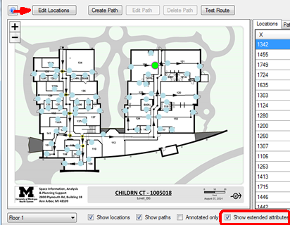
Add Locations
- Ensure that Show extended attributes is checked
- Click the Edit Locations button
- Click on the map at each point that a user may wish to find. It is best practice to place the points on doorways to assist the software with navigation.
For each point that is placed, add additional information. It is vital to add a zone. Zones are sections of the map that the user must enter or efexit via egress. Typical zones are floors, which require an elevator or stair well to travel from one floor to another.
Another attribute column may be added to indicate what the point is (such as a room number). Attribute columns can be added via the option menu in the upper right. Attributes are used to tie the wayfinding object to a data source. If the directory is being populated by an Excel sheet for example, then the values of the wayfinding attribute must match those in the associate Excel column EXACTLY.

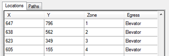
Egresses are used when multiple floors are visible on one map or when multiple maps are present. Egresses are used to connect two floors or maps together.
Any egress placed on a map must have a zone associated with it.
Since egresses connect zones, another egress must exist with the EXACT same value in the egress column. Examples of egresses include stairs, elevators, doors that connect building to building, or locations that lead to different maps (like a building map to a campus map).
Add Paths
- Ensure that Show extended attributes is checked.
- Click Create Path.
- On the map, click points along a path that the user should follow.
- Once a point is added, click and drag on it to move it around.
- To remove a point, hold the control key and click the point.
- To add a point mid-path, hold the alt key and click on the path.
- To complete the path, click Done.
- Add a zone to each path. The zone for the path should match the zone for the locations on this map.
- Repeat these steps for each path that needs to be added.
- Paths should follow these guidelines:
- Paths do not need to fall on an existing location. In fact, it’s best if they don’t.
- Paths should not intersect themselves.
- Paths should cross other paths when appropriate. Doing so will cause a yellow circle to appear, indicating the intersection.
- Paths do not have to reach all locations. The rules for wayfinding state that the software will follow the path until the closest point is reached to the location. At that point, the wayfinding will leave the path and connect to the location directly. This is why locations should be placed on doorways.
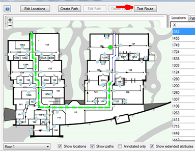
Test Route
- Click Test Route.
- Click two points on the map.
Note If there are multiple zones on one map, the software will prompt which zones are being traveled from and to.
The software will map a route between these two points based on the paths and egresses set up on the map.
You Are Here
The “you are here” beacon can be placed by directly entering the numeric coordinates of the point or by referring to a variable placed on each player. The variable method is recommended, especially for units with multiple players playing the wayfinding object. The variable method allows a unit to use one playlist of templates while utilizing different “you are here” locations on each player.
Determine the following for each "you are here” location needed:
- X,Y – This can be determined by hovering the mouse over the associated point and making note of the values appearing below the map.
- Map – This is the numerical number of the map that contains the “you are here” location. Map numbering starts at 0 (Floor 1 = 0)!
- Zone – This is the zone that the “you are here” location appears in.
Here are the two methods of placing the “you are here” location:
- Static – type the values X,Y,map, zone directly in to the field on the wayfinding content object.
- Dynamic (variable) – Type in a variable name in the appropriate field in the wayfinding object. Then, right click on the player and choose properties. Click the Variables button. Type the variable name in the Name field and then “X,Y,map, zone” in the Value field.
Connecting to Live Data
Most digital sign wayfinding maps have a live data object (Excel, CSV, SQL, etc.) associated with them. The live data object contains the list of people, places, or things that the end user wishes to find navigation to. To work properly, the wayfinding object must be called from this data using interactivity. This document assumes that a wayfinding object and a live data object have already been created.
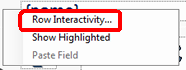
- Open the live data object layout properties by right-clicking the content object and choosing layout.
- Right click on the row in the layout and choose Row interactivity…
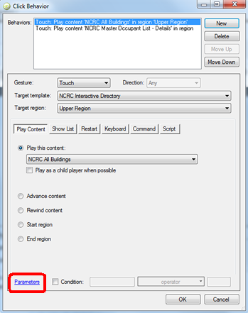
- Add a behavior. The behavior should call the wayfinding object.
- Once the behavior is created, click on the Parameters link near the bottom. This is how the live data object will tell the wayfinding object which item has been selected.
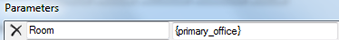
The parameter syntax is:
- Left field: column label of wayfinding object
- Right field: column label of live data object enclosed in {}
- Additional criteria can be added. SHOW IN SCREEN SHOT
- The destination marker can be modified to include data from the live data. Left column should be set to MarkerText, and right column should be value to show enclosed in {}.
- Preview the sign and test the directory and wayfinding. When previewing the sign, click on the player and choose preview in content manager. If things fail, there are several things to check:
- Run a test route on the map(s) that failed. Verify that the software correctly paths the route.
- Verify that the destination is in the correct zone. Compare this against the path that leads to it as well.
- Verify that the “you are here” location is correctly coded.
- Verify that the player was selected when “preview” was chosen. This is imperative when variables are used to code the “you are here”.
Changing Routes, Beacons and Transitions
Note Whenever a wayfinding object’s locations or paths are modified, the Show Extended Attributes box should be checked.
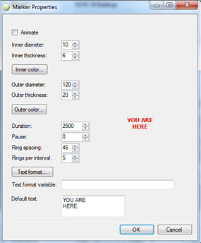
Marker color and animations can be changed via the wayfinding object properties window.
The marker properties window allows the user to change:
- Color
- Ping diameter
- Ping line thickness
- Ping color
- Ping duration
- Text of ping
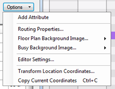
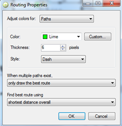
Routes and Egress lines can be modified using the Options menu in the wayfinding window. Click Options – Routing Properties…
- Routing behaviors
- Line thickness
- Line style
The advanced tab of the wayfinding properties window contains settings for:
- Inter-floor duration - how long each map appears before changing (for multiple map objects)
- Inter-floor transition – how the maps change and how long the change takes
- Animate route – Makes the software draw the line in real time to highlight where the route is. This can be repeated any number of times. The higher the time in ms, the slower the line animates on the screen.
Mapping to Multiple Locations
Occasionally there is a need to map multiple locations at once. An example of this would be restrooms. FWI software is able to do this. The software will map a line to the closest location and ping any others that meet the criteria.
- Create a wayfinding object.
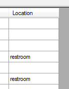
- Add an attribute for the locations that need to be mapped (example: Location).
- For each of these locations, give the attribute the same name (example: restroom).
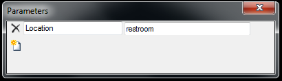
- When calling the wayfinding object via behaviors in interactivity, add a parameter that states attribute = value (example: Location | restroom).